Flexible Printed Circuit Board
When designing a Flexible printed circuit board, it’s important to consider testing processes that are integral to the process. These tests ensure the PCB meets electrical and mechanical specifications and is free from defects. They also help the PCB perform its intended function in various conditions.
The first step in testing a flexible printed circuit board involves checking for continuity in the circuit pattern. This can be done using an ohmmeter or by placing it in a test fixture that applies an AC voltage to the circuit and checks for current flow. The circuit can then be subjected to environmental testing. This test ensures that the PCB can withstand temperature, humidity, and vibration.
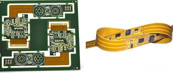
Flex circuit boards are used in a variety of applications, including wearable devices, automotive, and aerospace. The flexibility of the circuit allows it to be designed around contours and other shapes, which is important for these types of applications. It also makes it easier to incorporate multiple components.
What Testing Processes Are Integral to Flexible Printed Circuit Board?
Several different materials are used in the construction of Flex PCBs. Conductors, insulators, and dielectrics are the main components. Conductors are copper or other metals that allow electricity to flow through them. Insulators separate the conductors and are usually made of polyester or polyimide. Dielectrics are used to provide support and can be made of epoxy or acrylic. Lastly, solder mask and solder paste are used to protect the conductive material during assembly.
The Printed Circuit Board (PCB) is then assembled with the component parts using surface mount or through-hole technology. Once the components are mounted, they can be soldered to the circuit using reflow or wave soldering techniques. This final step is important for ensuring the quality of the finished product.
One of the most common issues with a Printed Circuit Board is its manufacturing process. This can cause problems that are not found during the design stage, such as incorrect stack-ups or improper bending radiuses. This can lead to a defective PCB that fails to meet its required electrical or mechanical specifications.
To avoid these issues, the designer should take into account the flex class and flex type when defining the design of the Printed Circuit Board. This will help them select the appropriate stack-up for the application and reduce the chances of mismatches between rigid and flex sections. Additionally, they should carefully consider the positioning of connectors to ensure that they are not subjected to excessive stress or vibration, which could cause them to fail.
Another important consideration is the use of a stiffener, which provides structural stability to the Printed Circuit Board. This can be made of FR4 or steel, and it helps prevent the board from bending too tightly during use. It can also prevent the board from slipping, which is an important safety feature for some applications.
There are a number of other important testing processes that are integral to the production of a Printed Circuit Board. These include visual inspection, functional testing, and X-ray inspection. Visual inspection is a key step in the process and involves examining the PCB for cracks, scratches, and other flaws. It is essential to use the proper tools and materials during the testing process in order to get a high-quality result.